Sonar Cable Specifications: Crucial Requirements for Military Projects

Defining the right offshore cable specifications for your Sonar System – how do you determine crucial requirements for your specific project?

In defense projects, the technical specifications are often very clear. But how can you make sure the cable perfectly fits the other components within your project? After all, each project is different and the same is true for the corresponding (sonar) cable construction.

To answer this question, it is important to know how the design process works. Which elements determine the construction of a qualitative naval cable? And which specifications are important for your specific project?

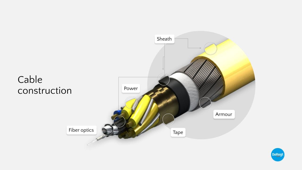
As each naval system requires a different cable construction, your unique requirements are translated into fit-for-purpose designs.

On this page, we explain how cable specifications work for defense projects.

Sonar Cable Construction: a breakdown

A sonar cable is a complicated construction, but it can be broken down into a few key components that most often recur:

  • Fiber optics – for data transmission
  • Power conductors – for electrical power
  • Insulation – around the electrical conductors
  • Sheaths/tapes – as separators between layers
  • Strength member – to transfer the load

For crush resistance, vulnerable components like electrical and optical components are laid up in the core of the sonar cable. Around the core, a strength member is wrapped. The cables are designed in a way that the load is transferred through the strength member, and not through the components. This means the strength member is designed to fail first, sparing the opto-electric core.


Another important aspect of sonar cable construction is the helical structure. The components are laid up in helices, with tapes and sheaths separating the layers. A helical structure enables the cable to bend and stretch without permanently deforming the electrical and optical components. The lay-up process that involves bundling components into helices, is called cabling.

Besides cabling, only one other process is essential to make a sonar cable: extrusion. With extrusion, the insulation layers are applied and the cable is sheathed.

A third process used in sonar cable construction is braiding, but this process is not required for every cable. Braiding is mainly used for reinforcing sheaths or shielding the electrical components (in that case a copper braid is used). Sometimes a braid is used as a strength member. This is the case when the applied loads are relatively small and a high degree of flexibility is required. Braids are also perfectly torque balanced, which could be required for certain specific cases.

Five types of Sonar System Requirements

Requirements form the basis of each cable system design. The most important requirements in defense specifications can be categorized into five types:

  1. Functional
  2. Operational
  3. Handling
  4. Environmental
  5. Interface

Functional Sonar System Requirements

These requirements are often directly linked to physical properties. For example, the operating depth has a direct impact on cable length. Density is also often an important functional requirement for a sonar cable. Heavy tow cables need to be heavy and therefore contain a steel strength member, while towed sonar array cables for submarines and light tow cables for variable depth sonar need to be as close as possible to the density of water, to make them neutrally buoyant.

Other examples of functional requirements are power requirements (voltage and current rating) and fiber optic requirements like bandwidth. These functions define the type, size, and the number of components and how they are integrated, causing them to have an enormous impact on the geometry of the sonar cable.

Operational Sonar System Requirements

These requirements are all about the operation. To manufacture a fitting cable, our experts need to know about towing loads, the number of cycles, the speed of the vessel, and operating depth. Usually, the operational data leads to the actual design life or mean time between failure. Speed and depth changes lead to load variation, and waves and ship motions also lead to bend stresses.

Knowing the required operating loads is important, as they define the maximum workload of the cable and have a direct impact on the required strength. The maximum workload is defined as the load necessary to stretch the cable by 0.6% (further stretching will cause permanent deformation of components). Often the strength member of the cable is determined by the maximum workload.

For military applications, the Survival Load is an important operational sonar system requirement. This is an indication of the load that can be applied to the cable a small number of times without degrading the cable’s performance to an unacceptable level. For most cables, this load relates to an elongation of between 0.8% and 1%. Usually, the cable can not be subjected to this load more than 5 or 6 times.

Handling Sonar System Requirements

Also important to know before designing a (sonar) cable system, are details on the handling system. Examples of handling requirements are the dimensions of the winch, the sheave wheel, and fairleads. The radius of the handling equipment directly impacts the required minimum bend radius of the cable.

The deployment and recovery loads and the number of launches are other examples of handling requirements. When deployment and retrieval loads are high, steel is often the logical choice.

Verification of the handling requirements is almost always done by qualification tests, as these can usually not be verified by analysis.

Environmental Sonar System Requirements

Specifications in the Defense market are often packed with Environmental Requirements. These are requirements that are necessary to operate in certain areas – take the Black Sea for example. This often has to do with temperature, chemical resistance, and often references are made to international standards.

To verify these Environmental Requirements you can have very difficult and expensive tests done, but that is often not necessary at all. A lot can be demonstrated from analyses because our suppliers of materials have already performed environmental tests on the materials used in our cables. They have already tested which temperatures and chemicals their materials can handle. The materials we use in cables and terminations are normally suitable for temperature ranges of at least -40 to up to 85 degrees Celsius, complying with almost all temperature requirements.

Interface Sonar System Requirements

Requirements concerning the Interface are requirements about how the cable is connected with other components. They determine what the Termination should look like. Terminations consist of four main ingredients:

  • Strength Member Termination, where the load from the strength member of the cable is transferred to the termination.
  • Bend Protection, where the cable is protected from overbending or kinking right behind the rigid termination.
  • Water Seals, consisting of various types of seals to protect the cable and termination from water ingress.
  • The Connector, which is the direct interface to your system and is a key interface component to be precisely integrated.

Specifications Checklist

Afraid to miss important cable specifications that are crucial for your defense project’s success?

This is not surprising, given the large number of components you need to know about as an engineer. To help you out, our cable experts created a Specifications Checklist.

Download the free Specifications Checklist here

A clear Design Process: the key to a verified Sonar Cable

Setting up a clear design process provides transparency and structure. It makes sure you can always look back and have a complete grip on your specifications. Our designers use a design process that’s divided into five phases, each concluded with a review moment to carefully document the progress:

  1. Preliminary Design Phase
  2. Critical Design Phase (Detailed design and Design analysis)
  3. Prototype Phase (Building and Testing)
  4. Production Phase
  5. Continuous Optimization

Preliminary Design Phase

In the Preliminary Design Phase, the focus is on defining the requirements. Based on these, concept designs are developed. A Design Compliance Matrix (DCM) is created, in which the verification method for each requirement is listed. This specifies how compliance with each requirement will be verified. Following the DCM, the qualification test plan and what needs to be tested as part of the factory acceptance test (FAT) are defined.

During the Preliminary Design Review at the end of this phase, the specification and concept designs will be reviewed, and one of the concepts is selected. The specification is then frozen.

Critical Design Phase

During the Critical Design Phase a detailed design is made and the purchase specifications for the subcomponents are written. In the Critical Design Review (the CDR) the various designs are evaluated with the specifications. The design is then frozen again and all components are ordered for the production of the prototypes.

Prototype Phase (Building and Testing)

The Prototype Phase, known for building and testing, is also known as the Test Readiness Phase. Detailed qualification and test procedures are written, the test equipment is designed and the prototype is manufactured. At the Test Readiness Review, the test procedures are thoroughly checked. After this check, the qualification tests can start.

This phase is concluded with a functional and physical configuration audit, in which the test samples, test method, and test results are reviewed. Only when the prototype passes all tests and meets all specifications, the production phase can begin.

Read more about Testing and Validating

Production Phase

All paperwork for full production of the cable system is being developed. These so-called production papers and the production readiness are evaluated in the Production Readiness Review.

After that, the Production Phase is all about creating the first article and performing optimizations on this first version. Another review follows after building this, to make sure that all non-conformities are solved and all requirements are being met. After passing this review, we speak about a qualified design – meaning the design is frozen for possible repeat orders.

Continuous Optimization

The final stage is Continuous Optimization, as there is always room for improvement. This is (ideally) only about small optimizations discovered over time. Rigorous adjustments to the cable will result in new tests, which means you will have to repeat (a large part of) the previously described process.

This design process seems to take a lot of time at first glance, but in the long run, all these steps will be much more efficient than continuously making significant changes.

Changing Specifications: what to do

As described in the design process above, there are a couple of moments when the design is being “frozen”. This means that if the design is changed after that (for example, due to a change of direction from the client), the previous steps need to be executed again.

The further you are in the design process, the more painful changing specs becomes – especially after materials have been ordered. That’s why the design process and Design Compliance Matrix are designed to achieve a frozen specification and design before developing.

Good preparation is very important; determining clear specifications helps prevent required changes later on. Early Supplier Involvement also plays an important role in this.

Want to know more about Early Supplier Involvement, Strategic Partners, and thinking along on possible changes?

Read more

Webinar: Specify, test and validate your Naval / Sonar Cable

How do you stay as cost and time-efficient as possible in your cable design process?

Our R&D Manager shares important insights on (sonar) cable construction and a couple of proven verification methods in our webinar. Request your recording here and watch the most interesting parts any time you like: